"PhotoRobot" rėmo patefono surinkimas ir vartotojo vadovas
Šioje techninėje dokumentacijoje pateikiama vartotojo informacija ir instrukcijos apie "PhotoRobot Frame" montavimą, prijungimą, pagrindinį testavimą ir veikimą. Ji skirta padėti "PhotoRobot" klientams savarankiškai įdiegti savo įrenginį ir ateityje įtraukti gamybos linijų operatorius.
Svarbus: Pirmąjį "PhotoRobot" įrenginio montavimą visada turi atlikti "PhotoRobot" patvirtinta institucija. Institucijos, įgaliotos įdiegti "PhotoRobot", yra patvirtintas platintojas arba paties gamintojo atstovas.
Nata: Visada žiūrėkite "PhotoRobot" saugos informaciją ir instrukcijas, taip pat vadovą, kurį "PhotoRobot" pateikia konkrečiai su jūsų įrenginiu.
Rėmo patefono montavimas ir pirmas naudojimas
Sveikiname įsigijus "PhotoRobot" įrenginį! "PhotoRobot Frame" atspindi dešimtmečius sukauptą tiesioginę patirtį ir inovacijas automatizuotos gaminių fotografijos srityje. Tiek išradinga, tiek stilinga, mūsų komanda sukūrė "PhotoRobot" techninę ir programinę įrangą, kurios prioritetas yra jūsų verslas. Kiekvienas sprendimas yra pritaikomas taip, kad atitiktų unikalius poreikius, bet taip pat suteiktų naudos visai paruoštų sprendimų ekosistemai, palaikančiai "PhotoRobot" klientus. Tai reiškia, kad jūsų verslas gali būti tikras, kad visada rasite veiksmingą atsakymą į visus jūsų vidinius gamybos reikalavimus.
Sveiki atvykę į PhotoRobot. Toliau pateikiama informacija apie funkcinį technologijos veikimą, įskaitant instrukcijas, kaip savarankiškai surinkti ir pirmą kartą naudoti mašinų operatoriams.
Jei kyla problemų, kreipkitės į "PhotoRobot" trikčių šalinimą, kad gautumėte dažniausiai pasitaikančių problemų, susijusių su aparatūros diegimu, fotoaparatais, robotais, apšvietimu, redagavimu ir postprodukcija, sprendimų.
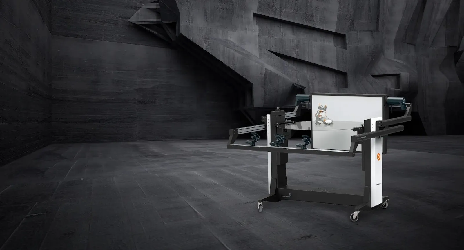
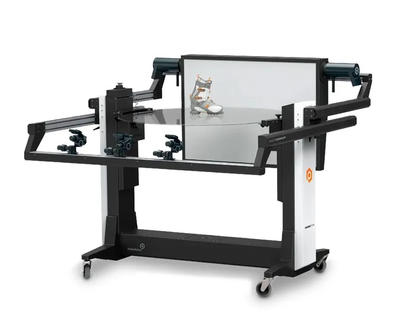
1. Produkto aprašymas - "PhotoRobot" rėmas
"PhotoRobot Frame" yra "viskas viename" įrenginys, sujungiantis motorizuotą patefoną ir roboto kameros svirtį. Jame yra dizainas, skirtas automatizuoti 360 laipsnių vaizdo ir nejudančių vaizdų fiksavimą 3D modeliavimui. Tiek fotoaparatas, tiek fonas tvirtinami priešinguose patefono galuose. Kamera ir fonas juda sinchroniškai su dviejų ašių 360 laipsnių patefono pasukimu. Tuo tarpu kamera išlieka visiškai priešinga fonui. Fotoaparatas gali fotografuoti ir iš apačios, patefono stiklo plokštės arba aukščiau. Tai leidžia automatiškai fotografuoti visas objektų puses, apačią ir viršų. Roboto ranka gali judėti nuo neigiamo 60 iki teigiamo 90 laipsnių.
Pagrindiniai "PhotoRobot Frame" komponentai:
- 130 cm skersmens optinio stiklo plokštė
- Dviejų ašių 360 laipsnių sukimosi dinamika
- Keliamoji galia 20 kg
- Integruota roboto ranka ir difuzinis fonas
- Automatinis kalibravimas vienu mygtuko paspaudimu
- Lengvas įrengimas bet kurioje studijoje, sandėlyje ar gamybos salėje
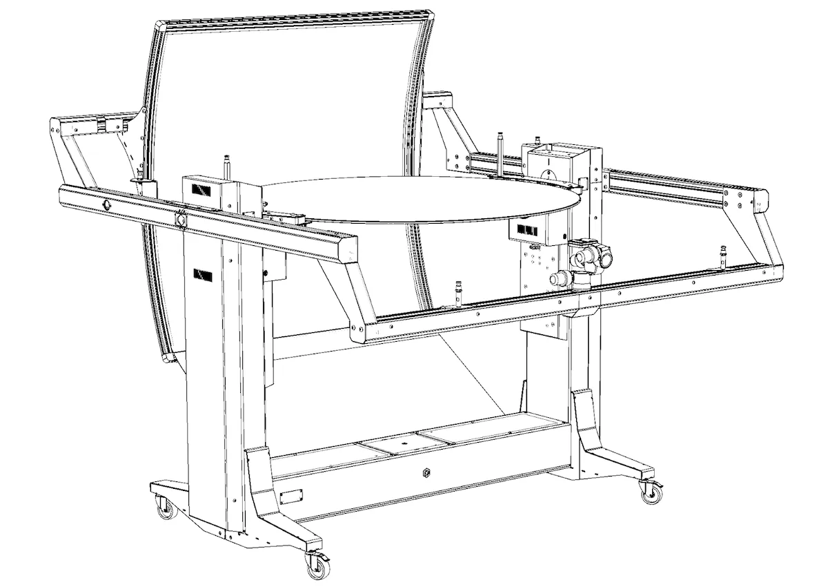
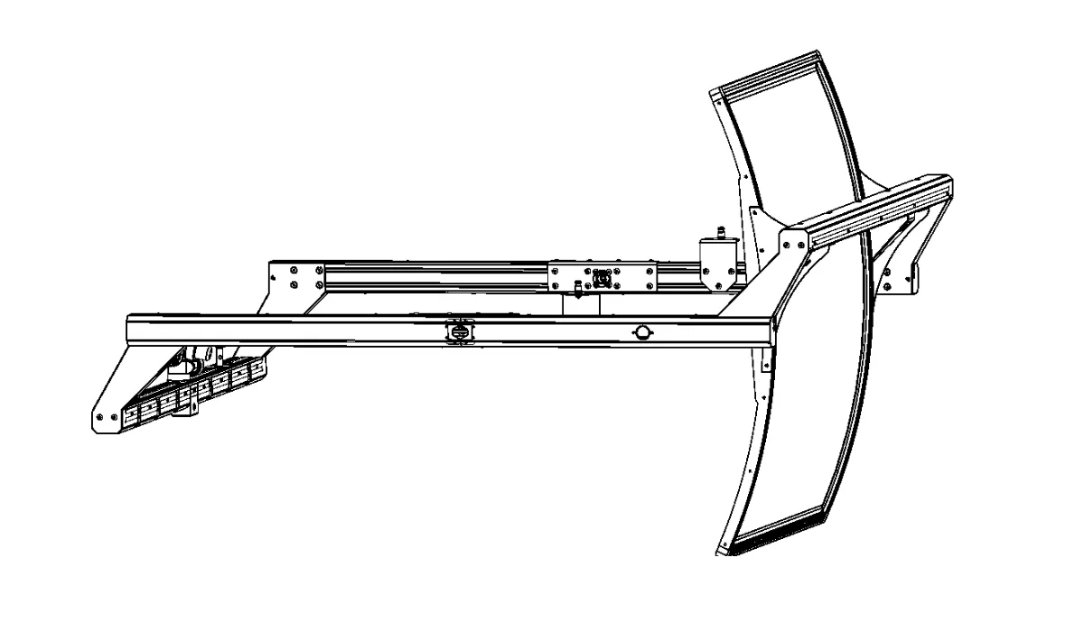
1.1. Roboto apžvalga - rėmo patefonas
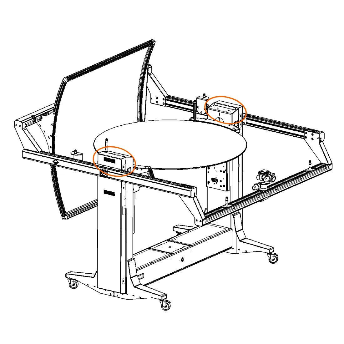
"Frame" robotas susideda iš trijų pagrindinių komponentų: valdymo bloko, mašinos korpuso ir svyruojančios svirties.
- Valdymo blokas yra neatsiejama maitinimo ir valdymo įrenginio dalis.
- Prietaiso mašinos korpusas palaiko motorizuotą patefoną su stiklo plokšte. Tuo tarpu mašinos korpuso pagrinde yra valdymo blokas ir ratukai judėjimui.
- Svyruojanti svirtis sumontuota aplink patefoną, kad būtų galima pritvirtinti roboto ranką ir difuzinį foną visada priešais vienas kitą. Tuo pačiu metu svyruojanti svirtis gali judėti nuo neigiamo 60 laipsnių žemiau stiklo plokštės iki teigiamo 90 laipsnių virš jos.
2. Robotų surinkimas
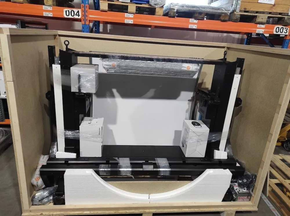
2.1. Išpakavimas ir paruošimas montavimui
2.1.1. Jei "Frame" robotas buvo pristatytas dėžėje, pirmiausia nuimkite viršutinį dėžės dangtį. Tada nuimkite galinį dangtelį.
- Nata: Jei robotas buvo pristatytas kito tipo konteineriuose, vadovaukitės konkrečiomis išpakavimo instrukcijomis, susijusiomis su pristatymu.
2.1.2. Išimkite iš dėžutės visas dalis aplink rėmą ir stiklo plokštę.
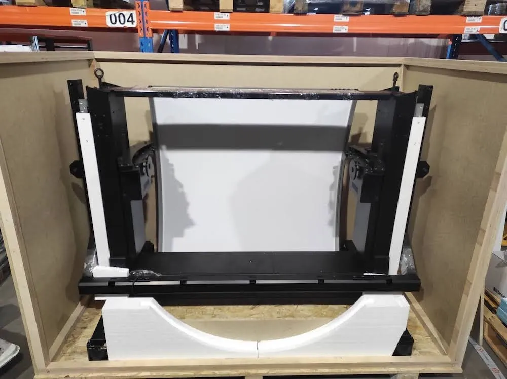
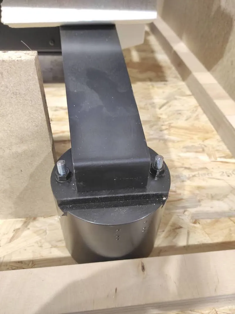
2.1.3. Tada suraskite ir atsukite dvi veržles nuo kiekvieno iš keturių juodų pagrindų.
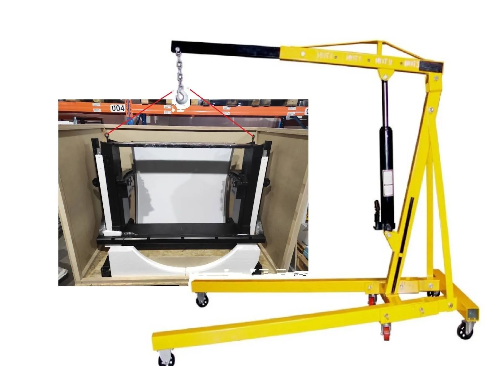
2.1.4. Naudokite kėlimo stropus, kurių keliamoji galia yra 400 kilogramų, ir perverkite stropus per rankenas viršutinėje roboto skeleto dalyje. Tada robotui pakelti naudokite bet kokį kėlimo įrenginį, pvz., šakinį krautuvą ar rankinį kraną.
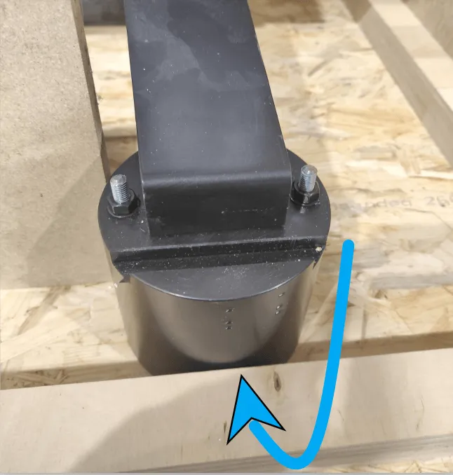
2.1.5. Tada atsukite keturis juodus pagrindus nuo apatinės mašinos kojų pusės ir nuimkite kiekvieną.
2.1.6. Tarp dėžėje pristatomų priedų raskite keturis ratus. Tada pritvirtinkite ratus į anksčiau nuimtų keturių juodų pagrindų padėtį.
2.1.7. Patikrinkite, ar ratai tvirtai pritvirtinti. Dabar bus galima roboto judėjimą ant ratų.
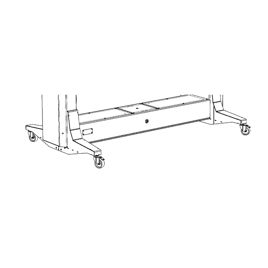
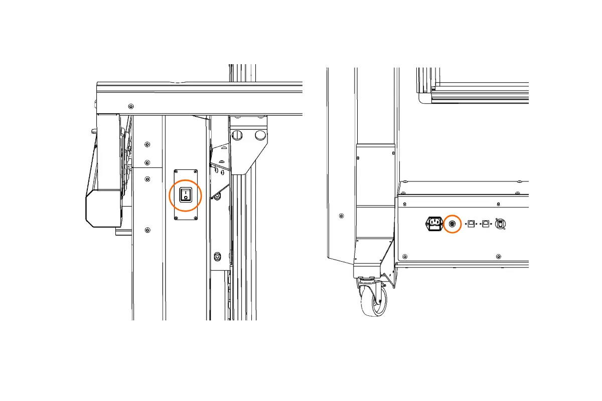
2.1.8. Atsižvelkite į priekinę ir galinę roboto puses. Galinėje pusėje yra maitinimo jungiklis ir elektros lizdas maitinimo laidui.
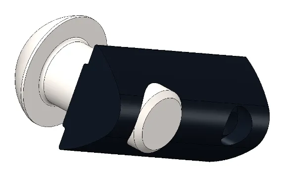
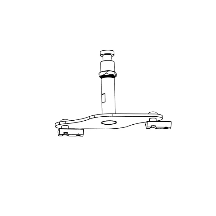
2.1.9. Suraskite svyruojančią svirtį dėžėje. Svyruojanti svirtis bus išardyta pristatymo metu.
a) Surinkta:
b) Išardytas:
- Nata: Kai kuriuose pristatymuose taip pat yra išardytas baltas fonas. Tokiu atveju žiūrėkite vėlesnį skyrių Fono mazgo konfigūracija (2.9.).
2.2. Rėmo prijungimas prie tinklo
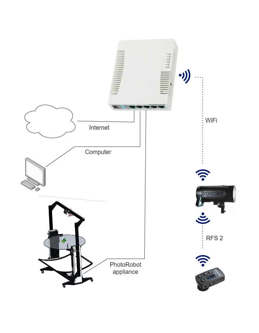
Sumontavę ratus ant rėmo įrenginio, įsitikinkite, kad roboto maitinimo jungiklis yra išjungtoje padėtyje. Tada įkiškite maitinimo laidą į elektros lizdą. Tada naudokite tinklo rinkinį, pateiktą kartu su robotu, ir prijunkite bent internetą, kompiuterį ir "PhotoRobot Frame". Ryšio schema turėtų būti tokia, kaip nurodyta šioje infografikoje.
2.3. Įrenginio įjungimas
2.3.1. Prijungę įrenginį prie interneto ir kompiuterio, įjunkite maršrutizatoriaus maitinimą. Tada palaukite maždaug 2 minutes, kol maršrutizatorius įsijungs ir pradės veikti.
2.3.2. Kai maršrutizatorius veikia, įjunkite kompiuterį, tada paskutinį veiksmą įjunkite "Frame" robotą.
2.4. Raskite "PhotoRobot" IP adresą LAN
2.4.1. Toliau suraskite PhotoRobot IP adresą LAN tinkle. Norėdami rasti FRAME ir kitų PhotoRobot įrenginių IP adresą, PhotoRobot Locator programa yra integruota tiesiogiai CAPP. Tai leidžia lengviau ieškoti ir identifikuoti valdymo blokus tinkle nenaudojant išorinių programų. Įsitikinkite, kad naudojate naujausią CAPP versiją, kad galėtumėte pasiekti šią funkciją.
Tada, norėdami identifikuoti robotą tinkle tiesiogiai CAPP, atidarykite vietinę CAPP versiją, eikite į Nustatymus ir spustelėkite Robotai / Valdymo blokai.
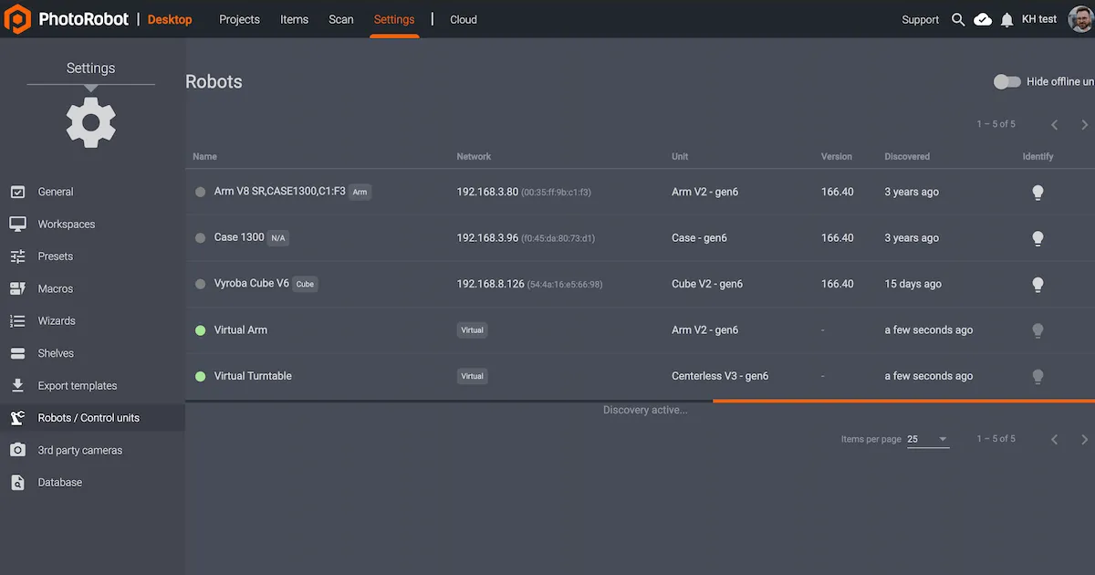
Meniu „Robotai / Valdymo blokai“ rodomi stulpeliai su pavadinimu, tinklu, bloku, versija, aptikimu ir identifikavimu kiekvienam robotui. Jei taškas kairėje roboto pavadinimo pusėje yra žalias, robotas yra prisijungęs. Spustelėjus roboto lauką, atsidarys roboto svetainės sąsaja. Tai taip pat privers roboto valdymo bloko LED lemputę mirksėti žaliai, kad būtų lengviau jį identifikuoti.
Jei klientui reikalingas išorinis programos atsisiuntimas, PhotoRobot Locator taip pat galima atsisiųsti iOS įrenginiams iš PhotoRobot paskyros atsisiuntimų.
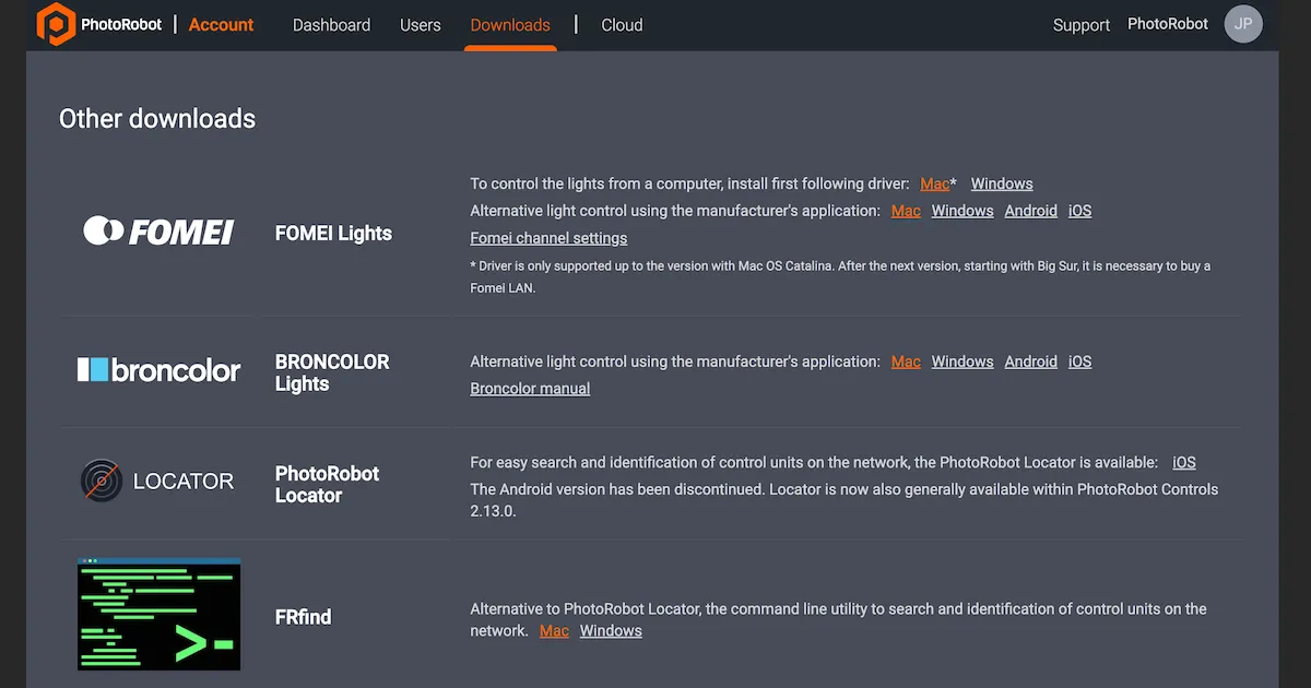
Pastaba: „PhotoRobot Locator“ „Android“ versija buvo nutraukta.
Arba yra FRFind komandinės eilutės įrankis, skirtas MacOS arba Windows, skirtas ieškoti tinkle ir identifikuoti PhotoRobot valdymo blokus. Nuorodas FRfind atsisiuntimui taip pat rasite PhotoRobot paskyros atsisiuntimų puslapyje.
2.4.2. Ieškokite PhotoRobot tinkle ir nukopijuokite jo IP adresą, kai įrenginys bus rastas. Tada įklijuokite PhotoRobot IP adresą į bet kurią vietiniame kompiuteryje atidarytą žiniatinklio naršyklę. Tai atvers paslaugos GUI, kuriame rodoma pagrindinė vartotojo sąsaja, skirta PhotoRobot testavimui.
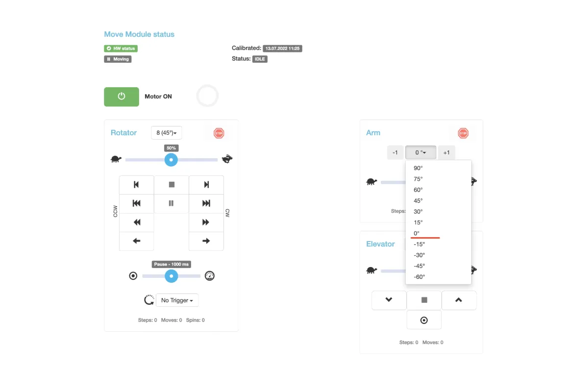
2.5. Įjunkite variklį ir judinkite roboto ranką
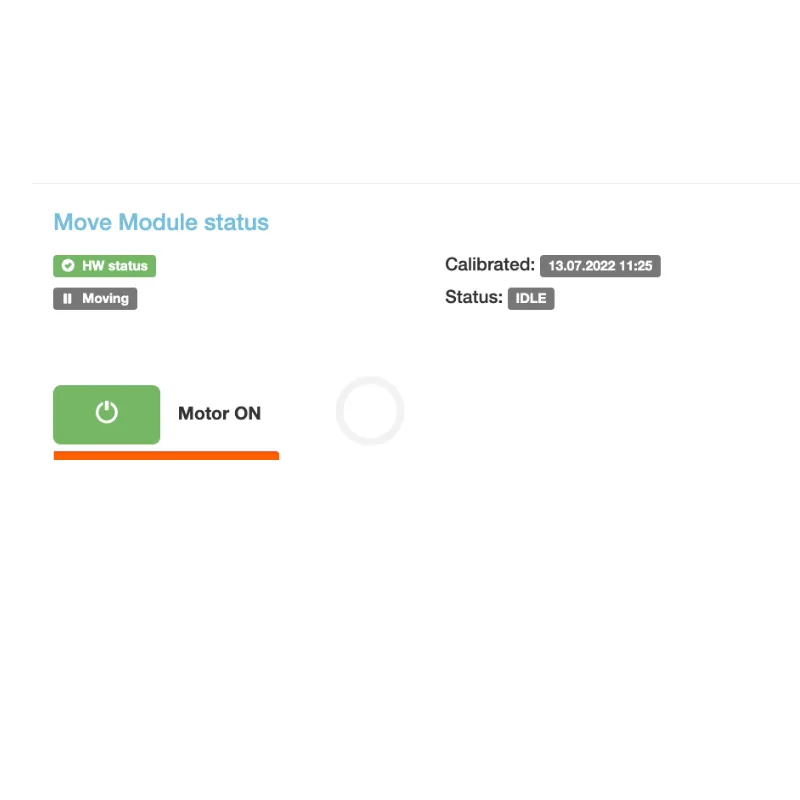
2.5.1. Aptarnavimo GUI naudokite variklio įjungimo mygtuką, kad įjungtumėte variklį.
2.5.2. Įjungę variklį, nustatykite svirtį į nulio laipsnių padėtį.
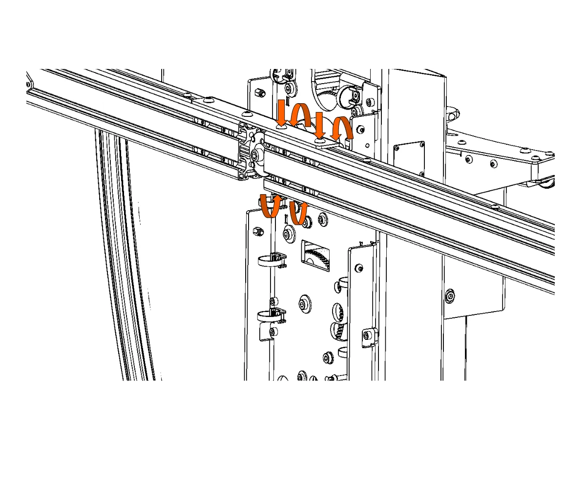
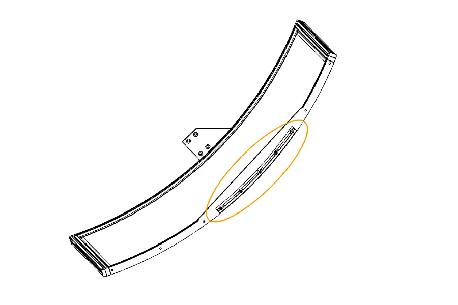
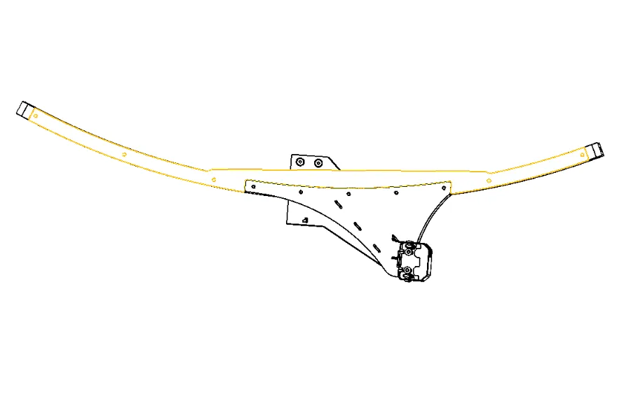
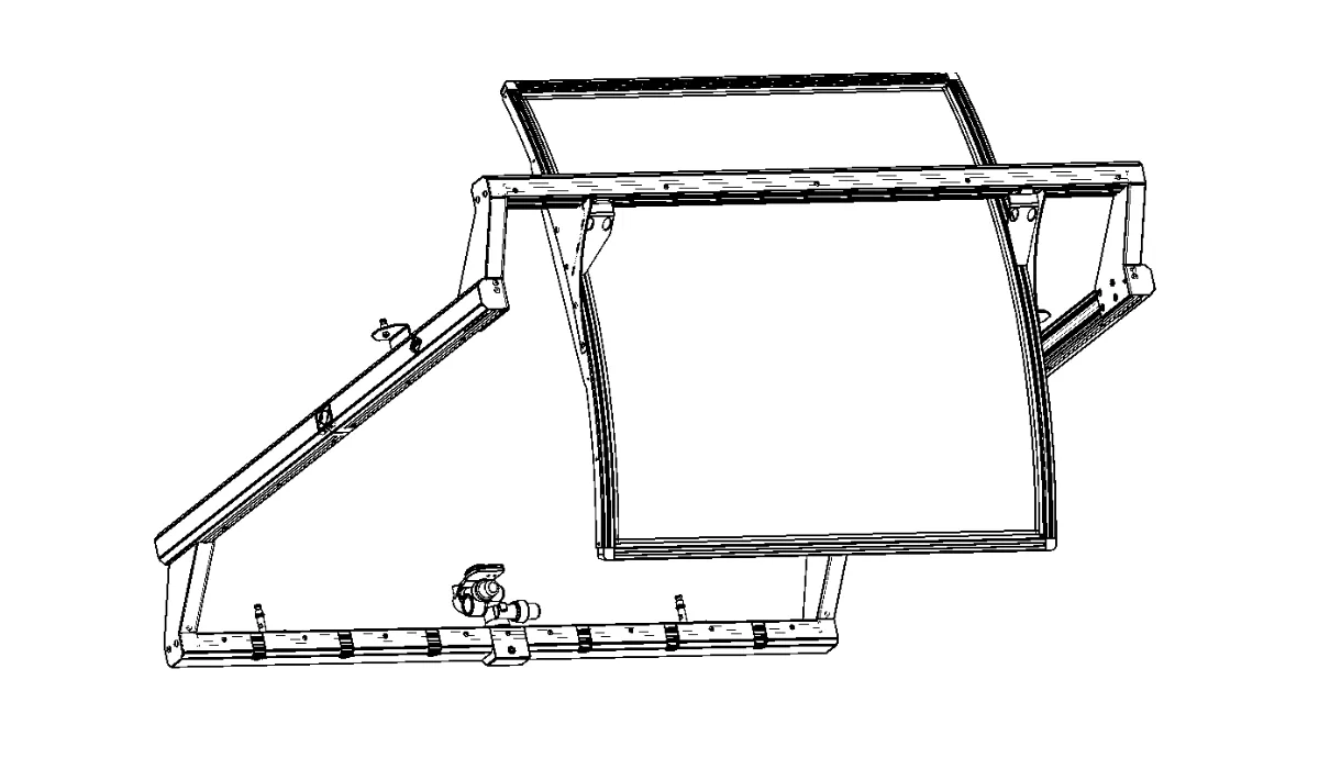
2.6. Pritvirtinkite priekinę svirties dalį
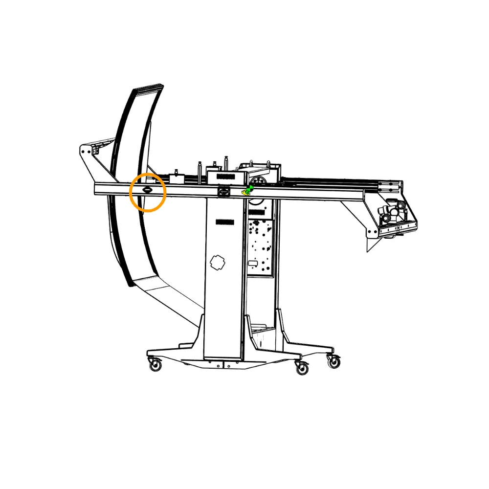
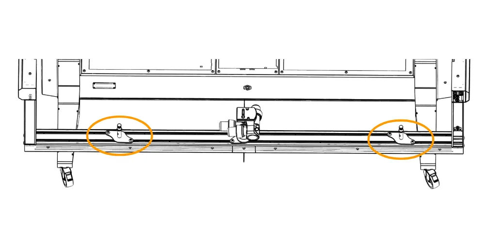
2.6.1. Kitas žingsnis yra priekinės svirties dalies montavimas. Priekinė siūbuojančios svirties dalis šioje diagramoje paryškinta oranžine spalva.
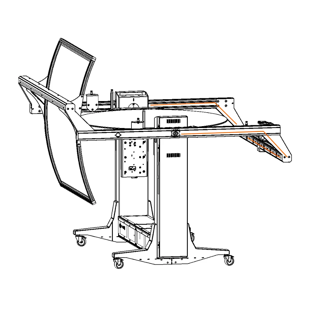
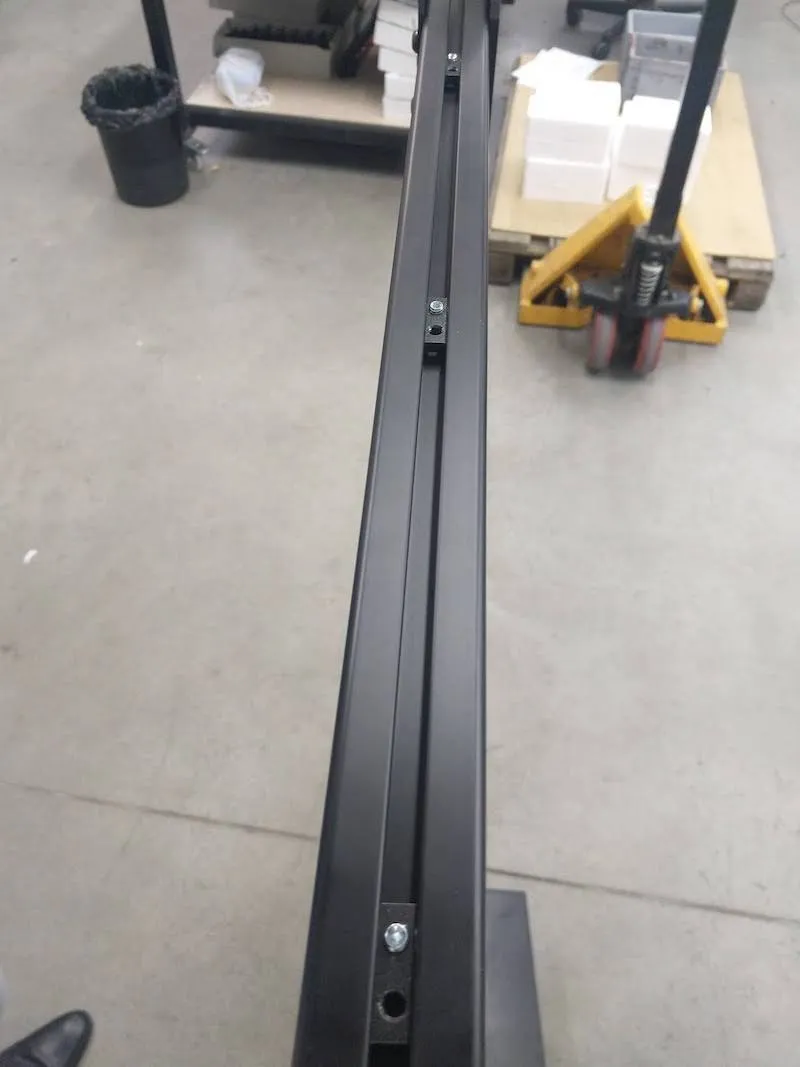
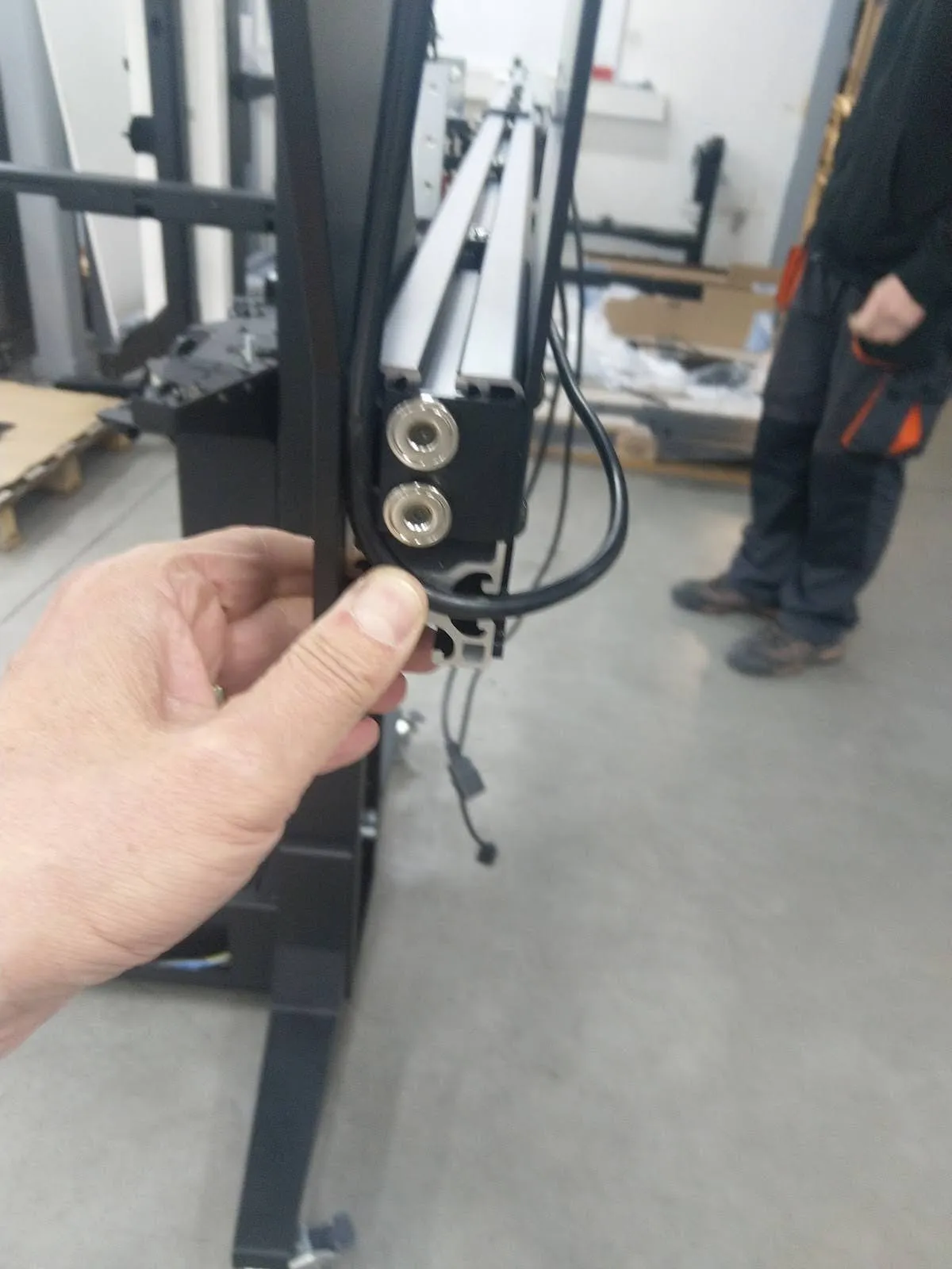
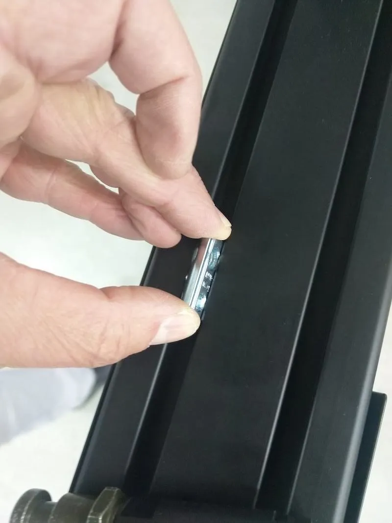
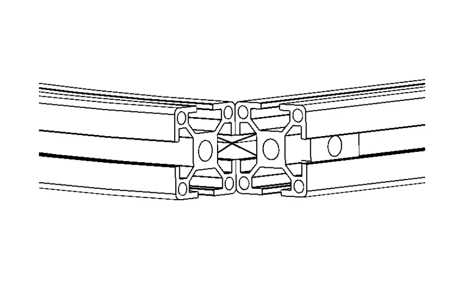
2.6.2. Įstumkite abi priekinės svirties pusės į 6 specialias sidabrines veržles. Pastaba: Kiekvienoje svyruojančios svirties pusėje yra 2 eilės po 3 veržles.
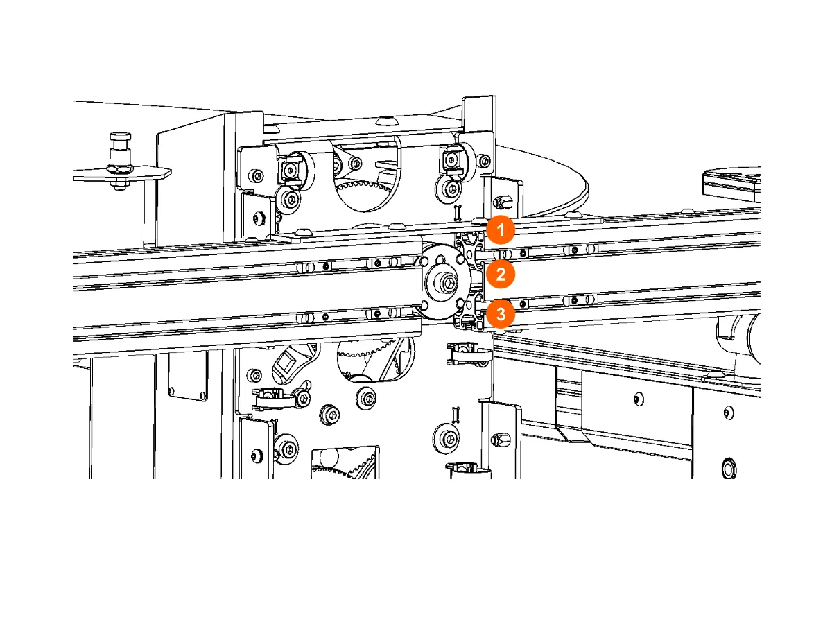
2.6.3. Abi svirties pusės sujungiamos taip, kad jos būtų lygios centrinei ašiai.
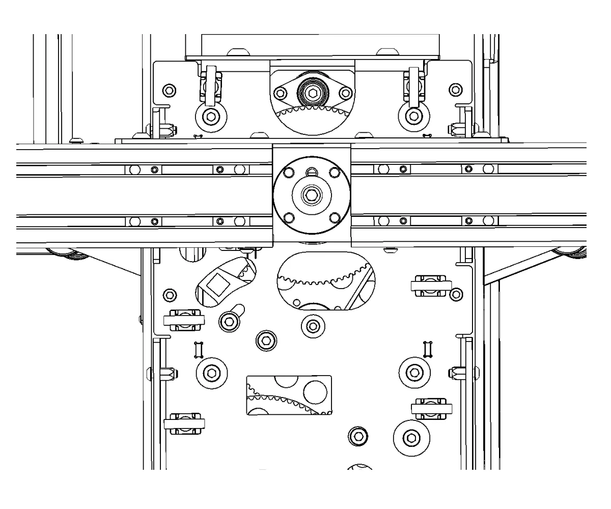
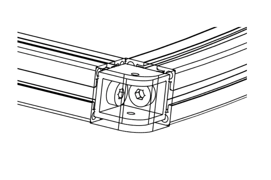
2.6.4. Šeši varžtai įsukami į veržles, jungiančias priekinę svirties dalį su centrine ašimi.
2.6.5. Tada tvirtai prisukite jungiamąsias rankos dalis ant abiejų "Frame" roboto pusių.
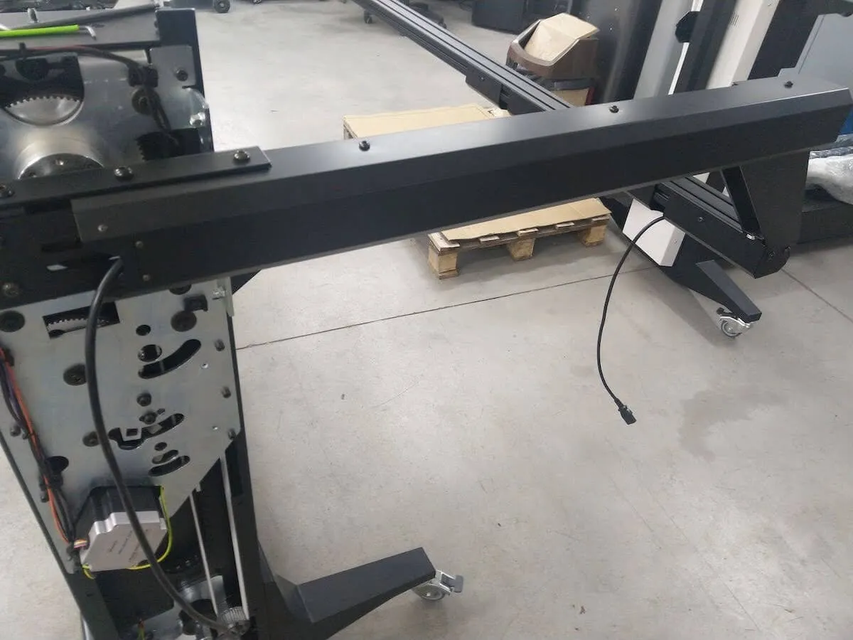
2.7. Sumontuokite baltą dangtelį ir paruoškite maitinimo kabelius
2.7.1. Kai priekinė rankos dalis yra tvirtai pritvirtinta, pritvirtinkite baltą dangtelį ant abiejų roboto pusių.
2.7.2. Tada suraskite 4 maitinimo kabelius, kurių kiekvienas yra 5 metrų ilgio žibintams maitinti.
2.7.3. Įkiškite vieną trosą per priekinę kairę svirties pusę.
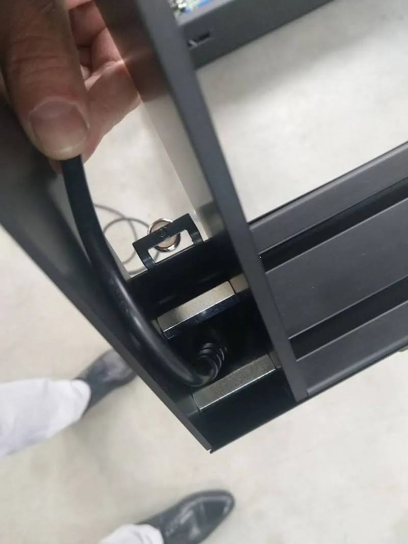
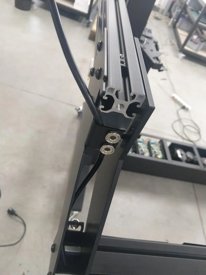
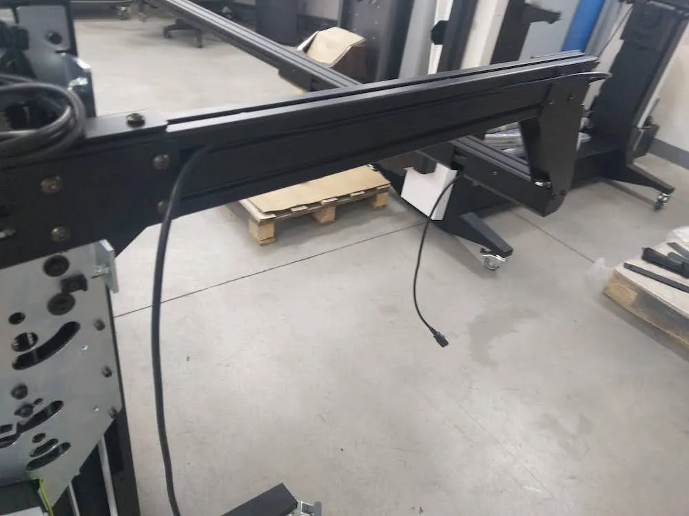
2.7.4. Suraskite lakštinio metalo dangtį ir uždėkite jį ant kabelio. Tada viršutinėje pusėje pritvirtinkite 3 varžtus, o apatinėje - 3 varžtus.
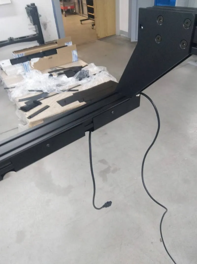
2.7.5. Prieš tęsdami kito kabelio sriegimą per mašinos rėmą, švelniai ištiesinkite kabelį.
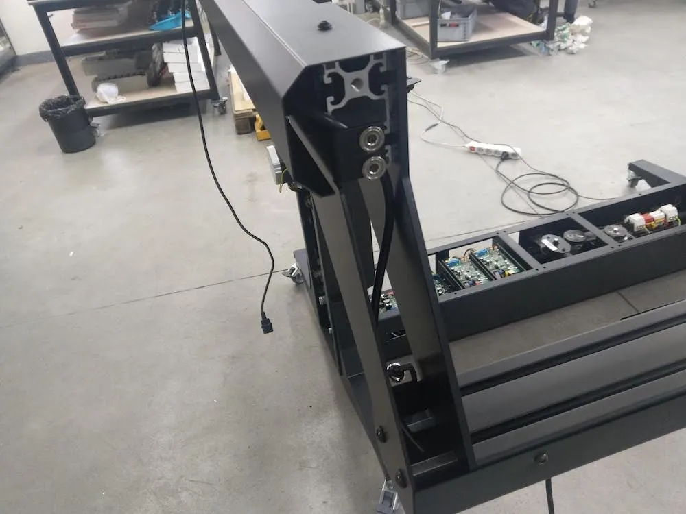
2.7.6. Paimkite kitą maitinimo laidą, kuris taip pat yra 5 metrų ilgio, ir perverkite jį per galinę kairę svirties pusę. Atlikite tuos pačius veiksmus, kaip ir montuodami pirmąjį laidą per priekinę kairę įrenginio pusę.
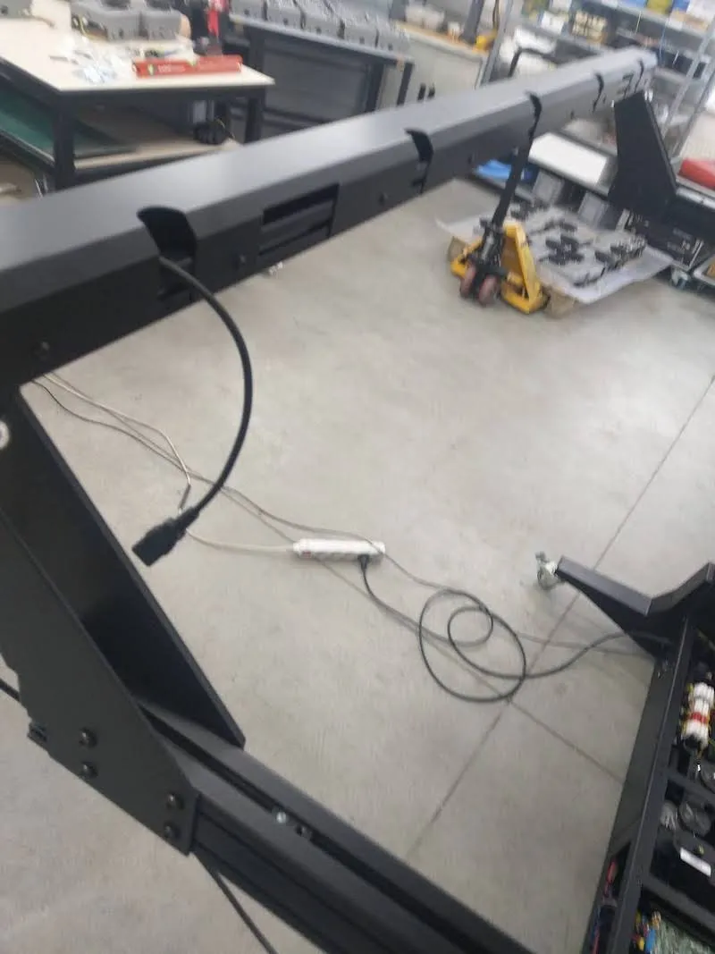
Nata: Naujesniuose "Frame" modeliuose yra 2 skylės foninės blykstės žibintų maitinimo laidams. Raskite juos kairėje ir dešinėje lakštinio metalo pusėse. Šių dviejų sričių kabeliai yra tik 3 metrų ilgio.
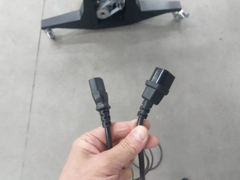
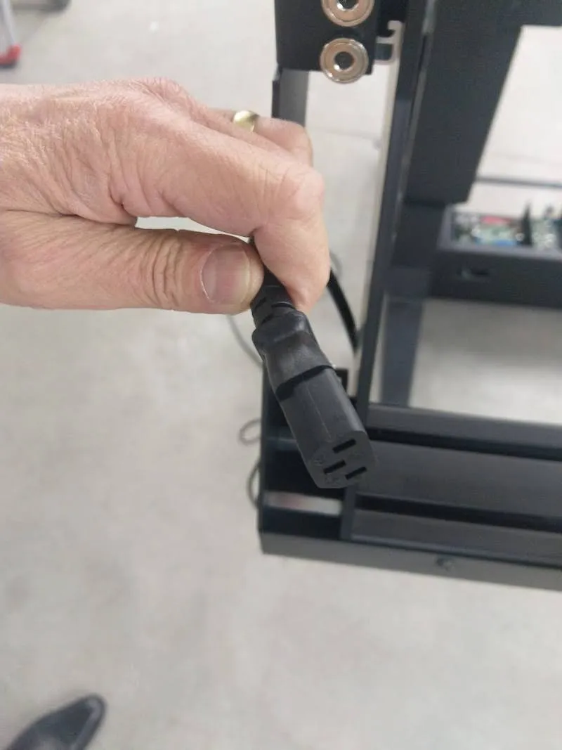
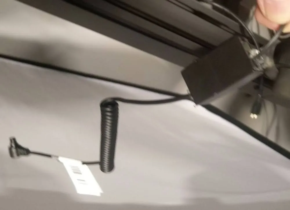
2.7.7. Dabar pakartokite ankstesnes surinkimo instrukcijas, kad surinktumėte dešinę svirties pusę. Vienintelis skirtumas yra tas, kad priekinėje dešinėje svirties pusėje yra du kabeliai su jungtimis. Jie palaiko užrakto kabelį su jungtimi ir lazerio maitinimo kabelį.
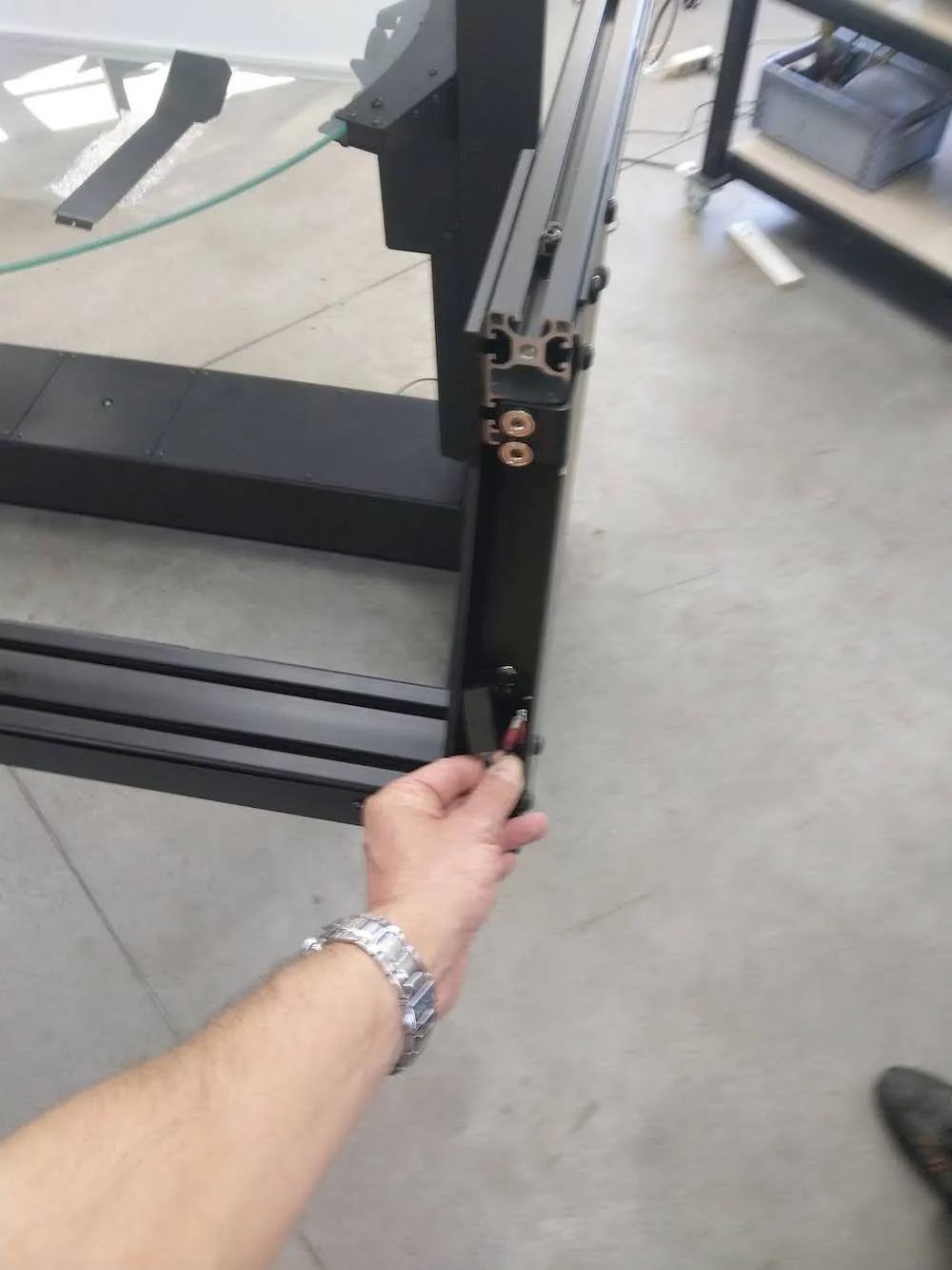
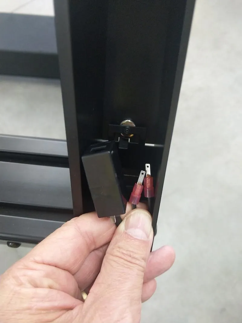
- Nata: Šių jungčių atitikmenys tvirtinami šalia svyruojančios svirties centrinės ašies. Prijunkite kiekvieną ir padėkite šalia maitinimo laido.
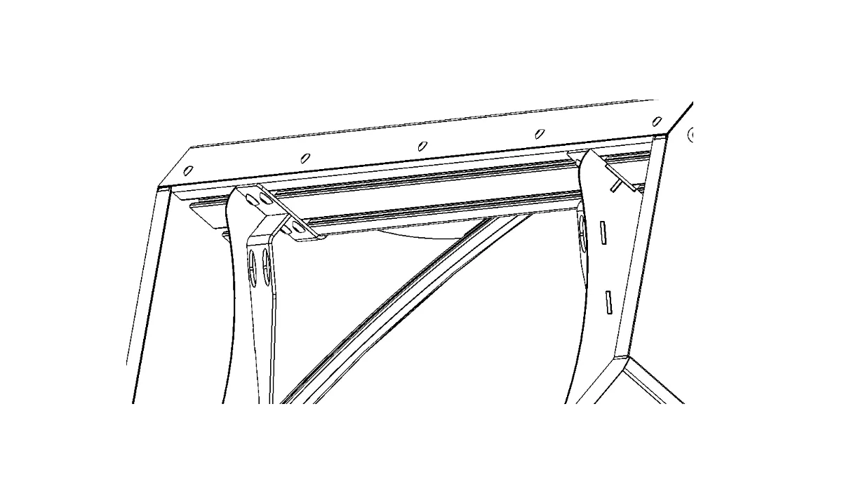
2.8. Sumontuokite svyruojančios svirties priekinių žibintų laikiklius
2.8.1. Surinkę svirtį, pasiruoškite pritvirtinti 2 priekinių žibintų laikiklius ant priekinės svirties dalies.
2.8.2. Pirmiausia įkiškite visus 4 specialius atraminius kuoliukus į priekinę svirties dalį.
2.8.3. Tada sumontuokite abu blykstės laikiklius.
2.9. Foninio mazgo konfigūracija
2.9.1. Jei fonas pristatymo metu atkeliavo išardytas, paruoškite fono mazgą. Kitu atveju pereikite prie 2.10 skyriuje "Foninis ryšys su siūbuojančia svirtimi" nurodytų veiksmų.
2.9.2. Norėdami paruošti fono mazgą, guminę armatūrą įsriegkite į fone įsiūtus tunelius.
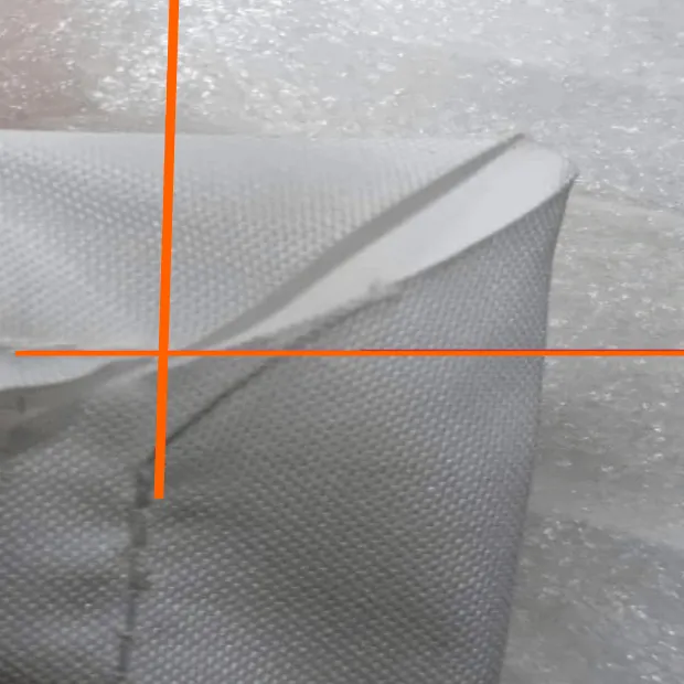
2.9.3. Tada sutrumpinkite guminius sutvirtinimus fono kampuose, kaip parodyta paveikslėlyje.
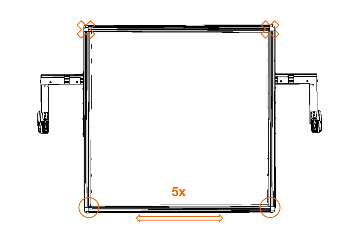
2.9.4. Išlenktos "X" formos profilio dalys įsriegiamos į fono šonus. Atkreipkite dėmesį į fono orientaciją. Atkreipkite dėmesį, kad fonas nėra kvadratinis; Jis yra stačiakampis.
2.9.5. Tada įkiškite vieną iš dviejų tiesių skersinių į foną, kad sukurtumėte "U" formos profilio dalis, kaip parodyta apatinėje paveikslėlio dalyje. Įkiškite 5 srieginių kaiščių gabalus į apatinį "X" formos profilio dalies kraštą, kad vėliau pritvirtintumėte prie juodo fono.
2.9.6. Sumontuokite movą 2 apatiniuose kampuose, tada prijunkite profilio dalis.
2.9.7. Įkiškite 5 sriegines jungtis į abi lenktų profilio dalių puses.
2.9.8. Sumontuokite antrą tiesią profilio dalį ir prijunkite kampus, pakartodami ankstesnius veiksmus.
2.9.10. Tada sumontuokite šoninius laikiklius, padėdami juos taip, kaip parodyta šablone (paryškinta mėlyna spalva), ir priveržkite laikiklius. Tada uždėkite visiškai sukonstruotą detalę ant galinės mašinos strėlės ir specialiais kaiščiais pritvirtinkite detalę.
2.9.11. Specialius kaiščius (jei jie yra jūsų mazgo dalis) galima įkišti į galinę strėlę neišardant kitų dalių.
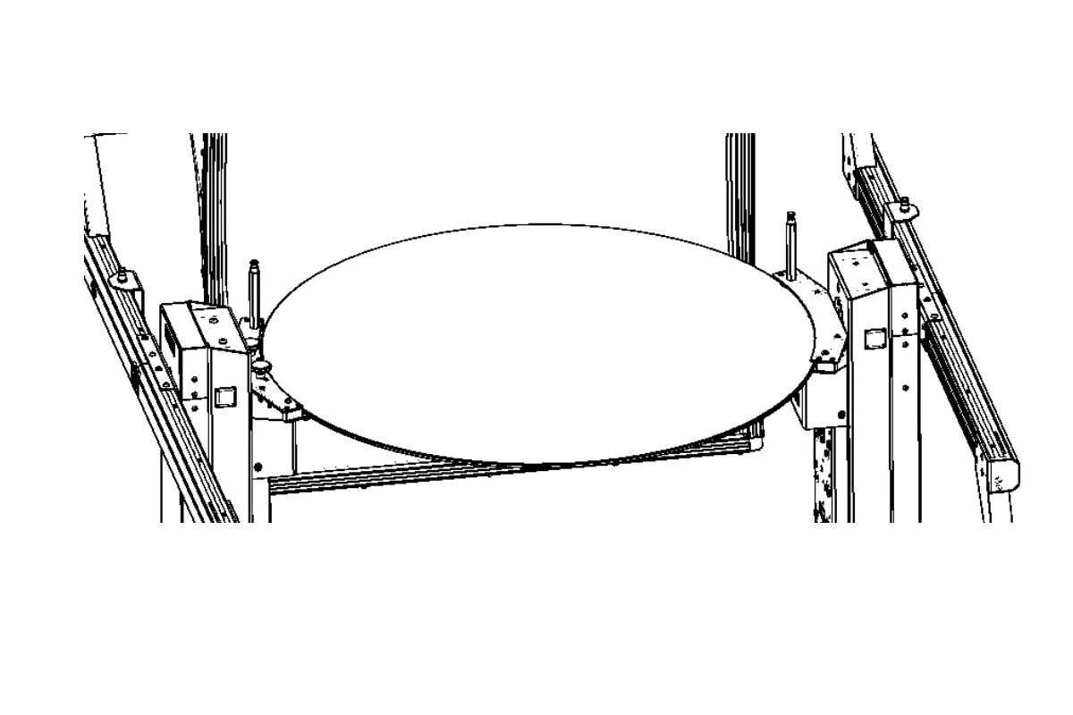
2.10. Foninė jungtis su svyruojančia svirtimi
2.10.1. Norėdami sujungti foną su svyruojančia svirtimi, pirmiausia pritvirtinkite foną galinėje svirties dalyje.
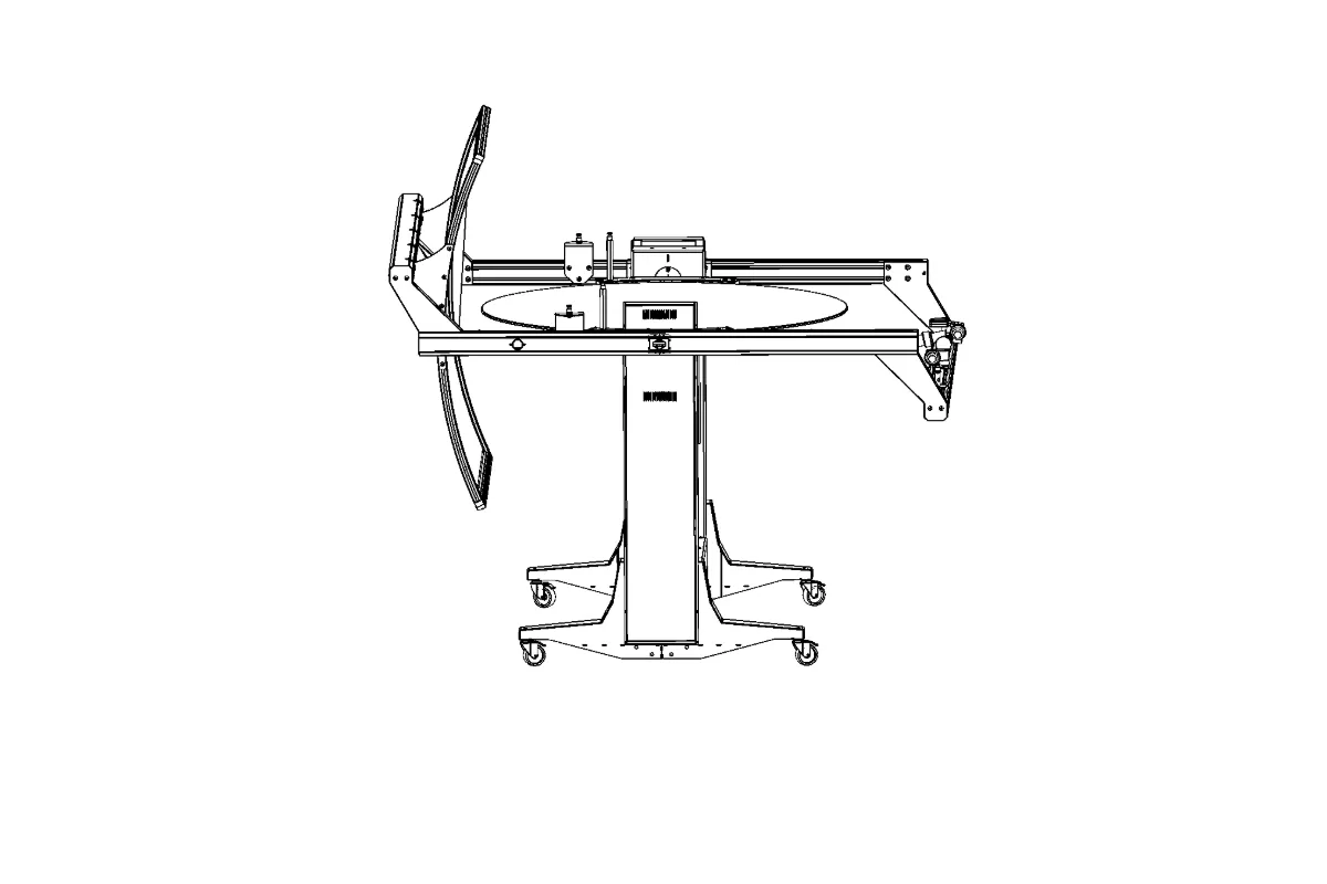
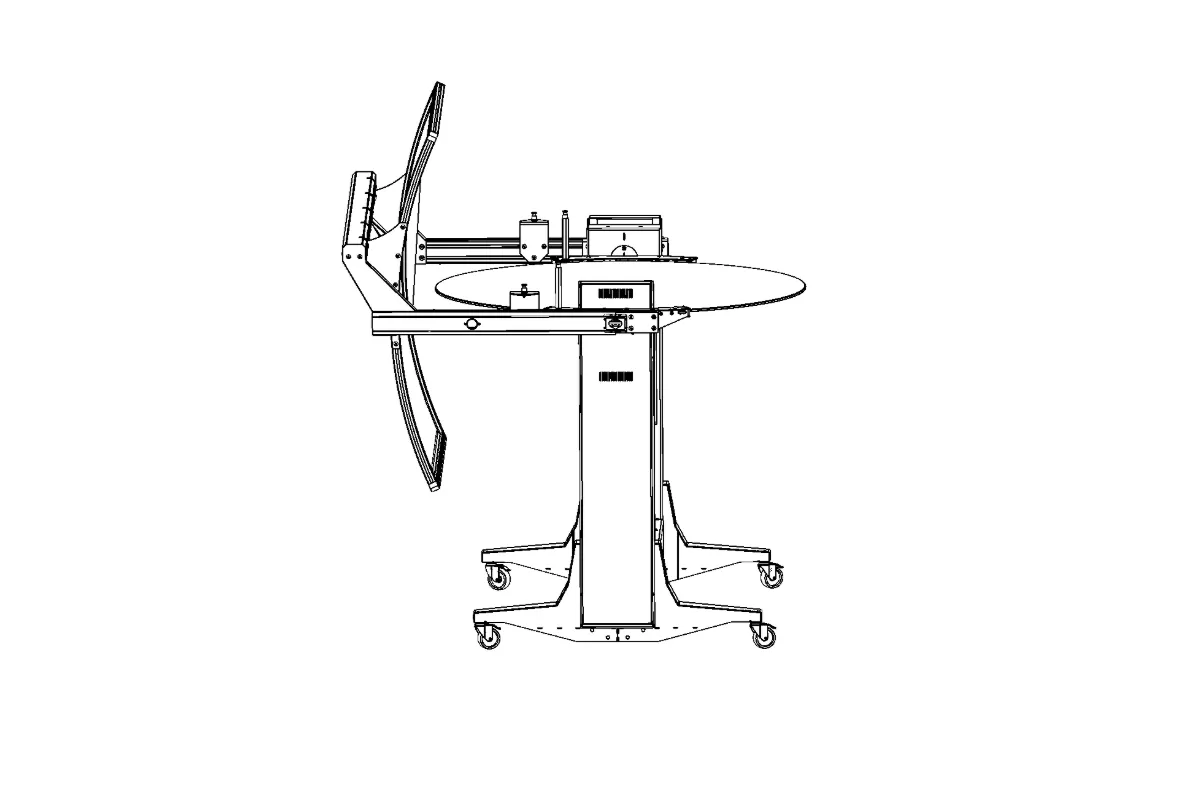
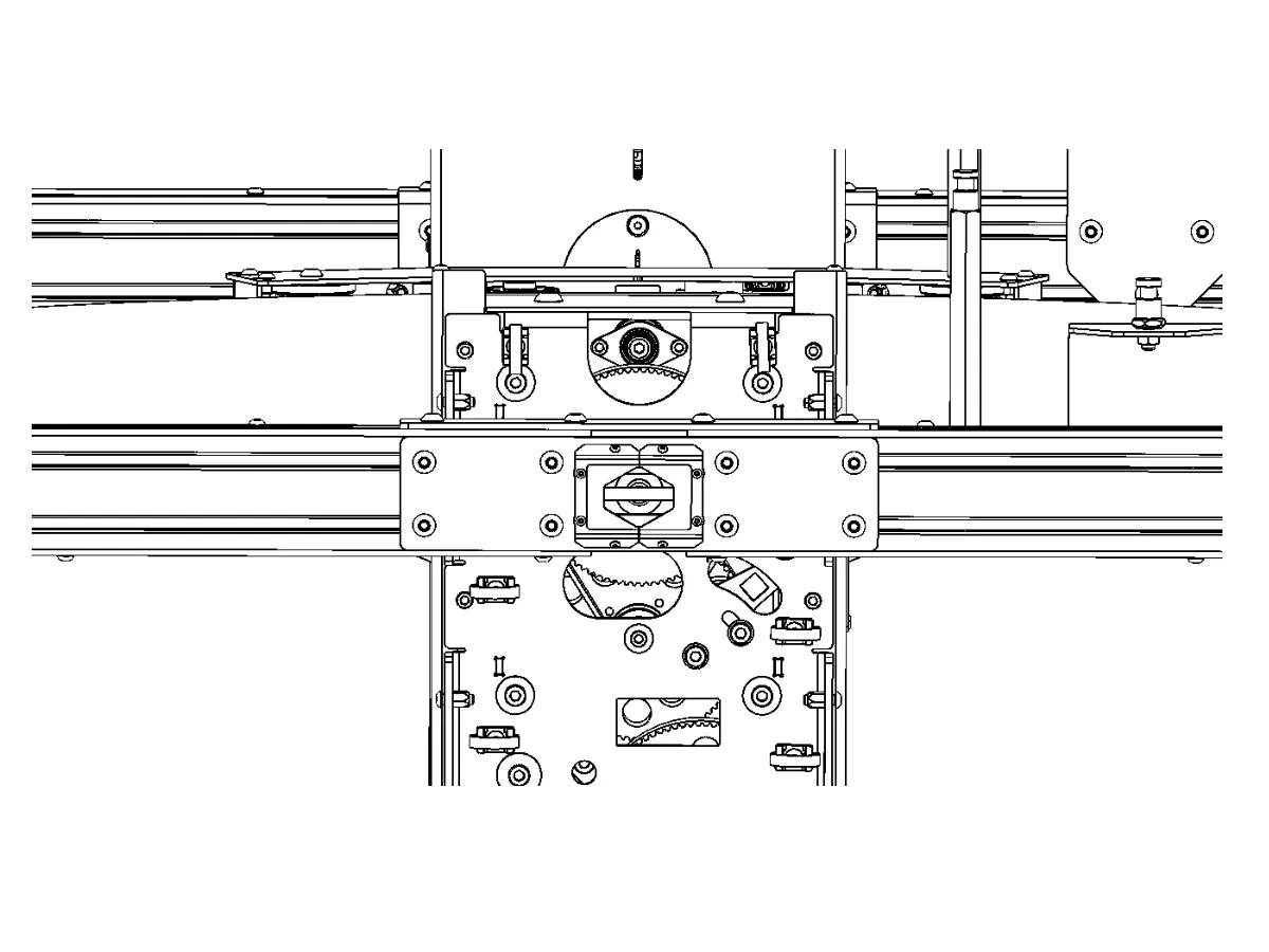
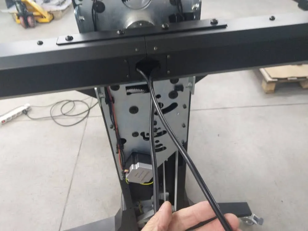
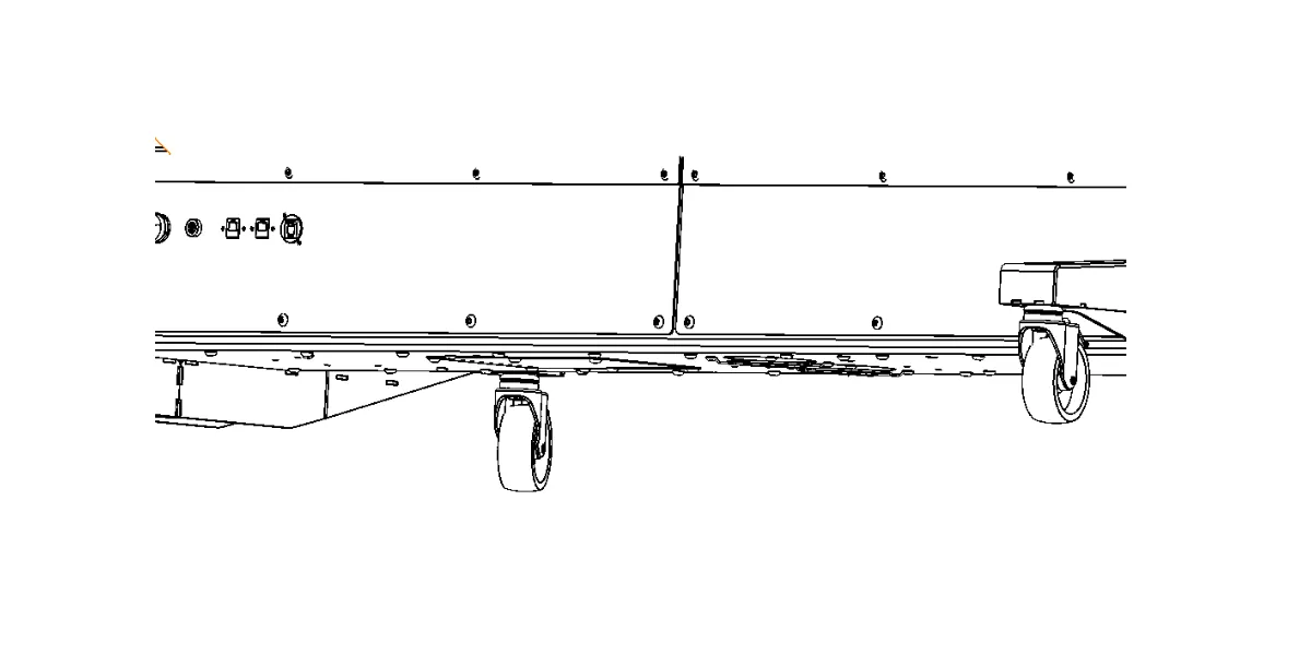
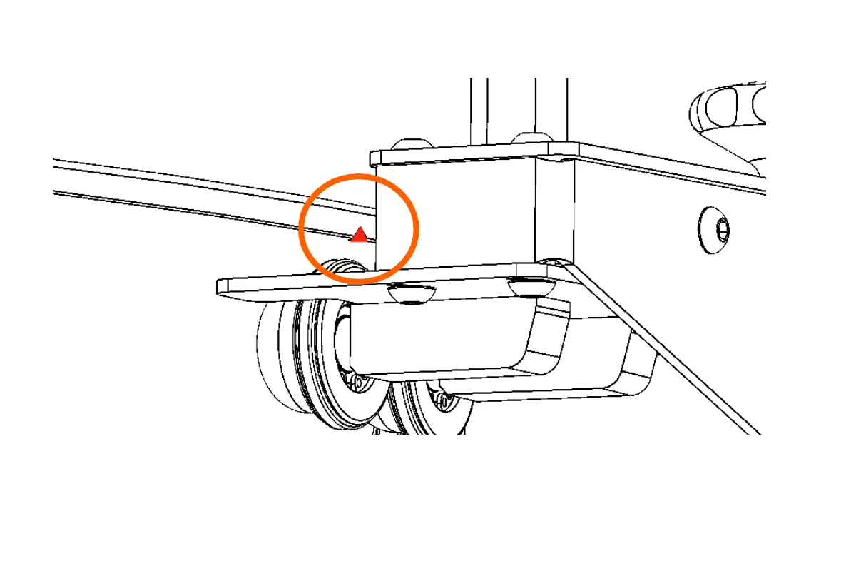
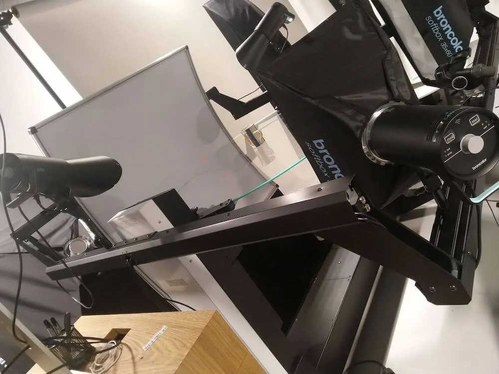
2.10.2. Tada pritvirtinkite juodą užuolaidą tarp fono ir apatinės roboto dalies. Norėdami tai padaryti, žiūrėkite šiuos išsamius įrenginio vaizdus.
a) Įrenginio apžvalga:
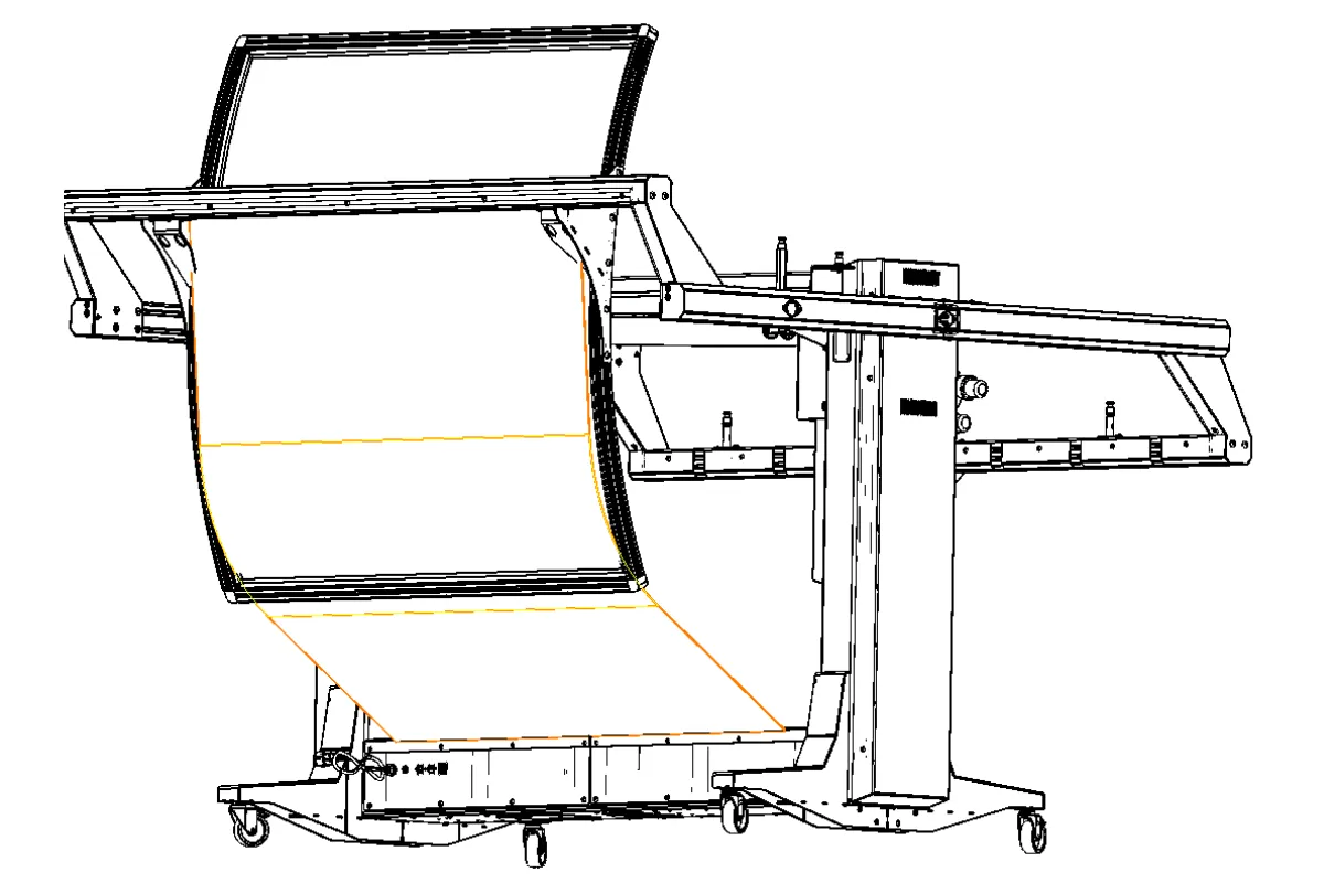
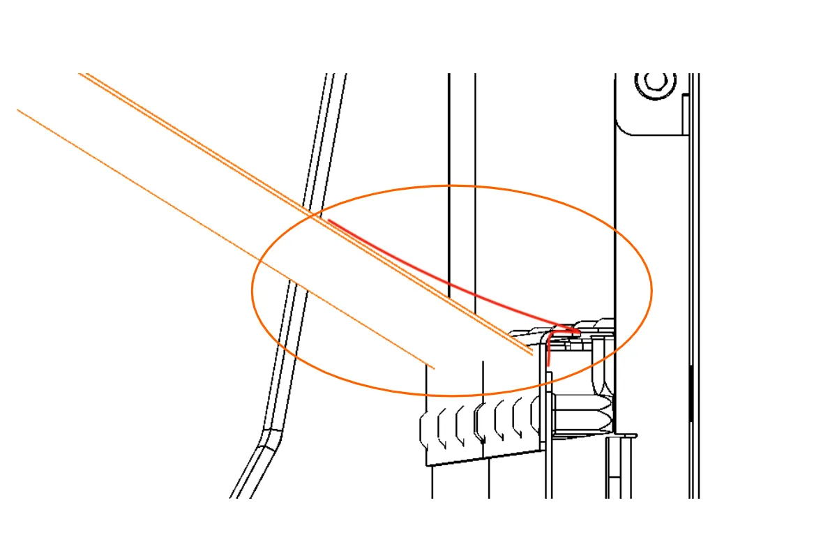
b) Įrenginio dugnas išsamiai:
c) Įrenginio apatinė užuolaidų linija:
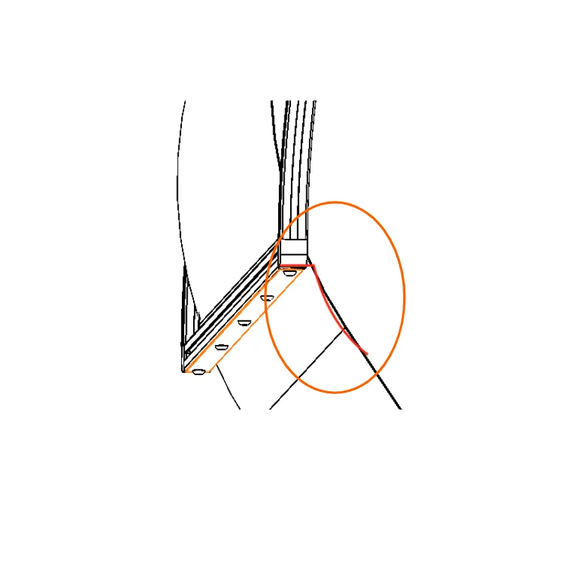
d) Įrenginio viršutinė dalis:
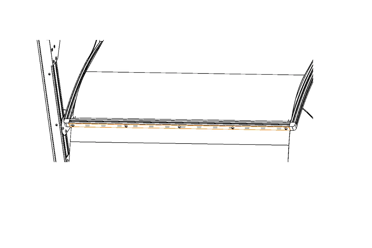
e) Įrenginio viršutinės dalies užuolaidų linija:
2.11. Stiklo plokštės tvirtinimas
Norėdami pritvirtinti "Frame" motorizuoto patefono stiklo plokštę, uždėkite stiklo plokštę ant roboto taip, kad plokštės krašte esanti įpjova būtų nukreipta žemyn. Atkreipkite dėmesį, kad įpjova turi būti nukreipta žemyn, kad prietaisas veiktų funkciškai.
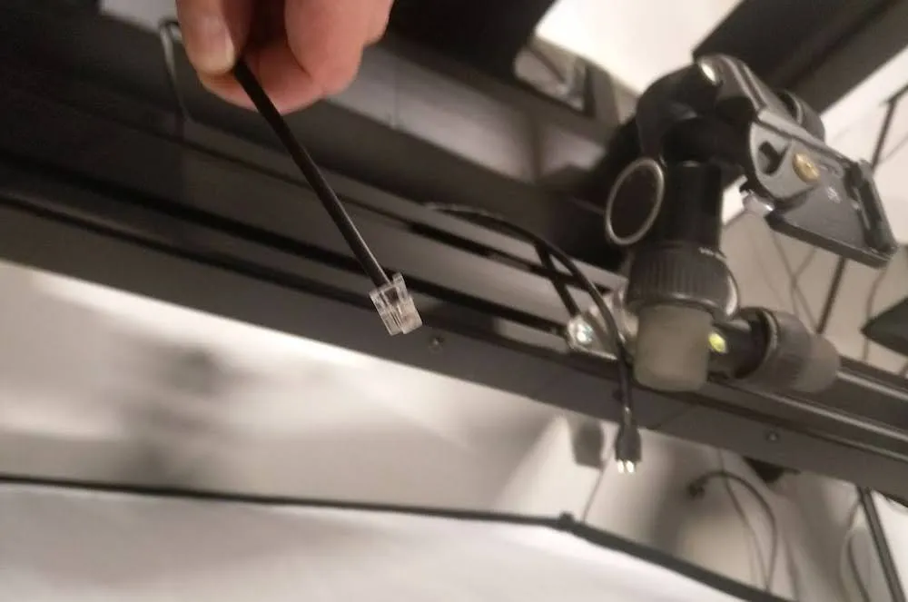
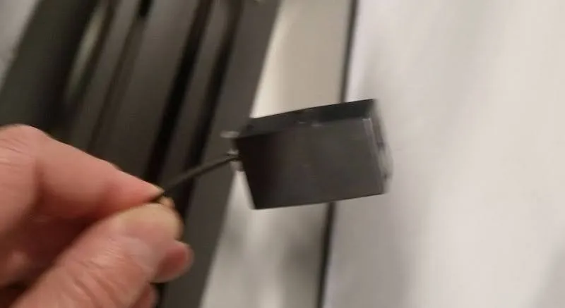
2.12. Fotoaparato prijungimas per užrakto kabelį
Fotoaparatui prijungti yra užrakto laidas, skirtas prijungti prie fotoaparato. Naudokite tinkamą užrakto kabelio jungtį, kuri tiekiama plastikiniame maišelyje, kuriame yra "Canon" lizdas, CN3 jungtys ir viena jungtis.
2.13. Softbox surinkimas
Galiausiai surinkite minkštąsias dėžes, pritvirtinkite jas prie žibintuvėlių ir pritvirtinkite visas lemputes prie įrenginio rėmo.
3. "PhotoRobot Frame" pirmą kartą naudojamas įrenginys
Kad "PhotoRobot" veiktų funkciškai, įrenginys turi būti prijungtas prie to paties tinklo kaip ir jį valdantis kompiuteris.
Svarbus: Žr. PhotoRobot pirmasis naudojimas ir pagrindinis testavimas išsamią dokumentaciją apie PhotoRobot prijungimą prie tinklo pirmą kartą ir vėlesnius diegimus.
Apskritai egzistuoja šie reikalavimai.
- Valdymo blokas turi būti prijungtas prie vietinio tinklo.
- Kompiuteryje turi veikti paslaugos GUI arba operatoriaus programinė įranga, vadinama _Controls.
- Kompiuteris turi prisijungti per tą patį tinklą kaip ir valdymo blokas.
- Tinkle turi būti veikiantis interneto ryšys.
Be to, elektros skirstymo sistemos parametrai turi atitikti reikalavimus (pvz., įtampa ir dažnis). Norėdami patikrinti elektros paskirstymo sistemos atitiktį, naudokite RJ45 jungtį, esančią valdymo bloko gale. Tinklo konfigūracijos reikalavimai yra tokie.
- DHCP serveris tinkle yra privalomas.
- Turi būti leidžiamas TCP prievadų 7777, 7778 ryšys.
- Turi būti leidžiamos UDP transliacijos 6666 prievade.
- Interneto ryšys yra privalomas.
- *. photorobot.com prieiga turi būti suteikta.
- as-unirobot.azurewebsites.net prieiga turi būti suteikta.
- Žr. PhotoRobot Networking Būtinosios sąlygos ir konfigūracija, kad patvirtintumėte tinkamą sąranką ir prireikus pašalintumėte triktis.
- Prijunkite maitinimo kištuką prie elektros lizdo.
3.1. Pagrindiniai bandymai po surinkimo
Norėdami išbandyti visas "PhotoRobot Frame" funkcijas po surinkimo ir prisijungimo prie tinklo, įveskite "PhotoRobot" IP adresą URL formatu į bet kurią vietiniame kompiuteryje atidarytą naršyklę. Bus atidaryta paslaugos GUI.
Nata: Naudokite IP adresą, gautą atlikus šio dokumento skyriuje "PhotoRobot" IP adreso paieška LAN (2.4.) nurodytus veiksmus.
3.2. Įjunkite įrenginį
3.2.1. Aptarnavimo GUI įjunkite variklį naudodami žalią maitinimo mygtuką Variklis įjungtas.
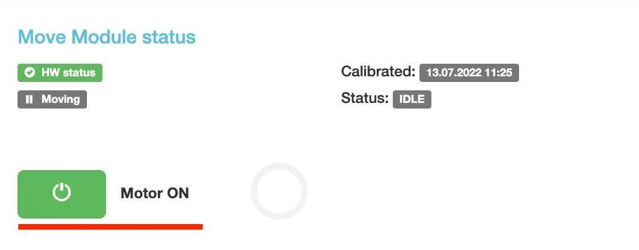
3.2.2. Tada sureguliuokite roboto rankos kampą bet kokiu norimu kampu naudodami paslaugų GUI sąsają.
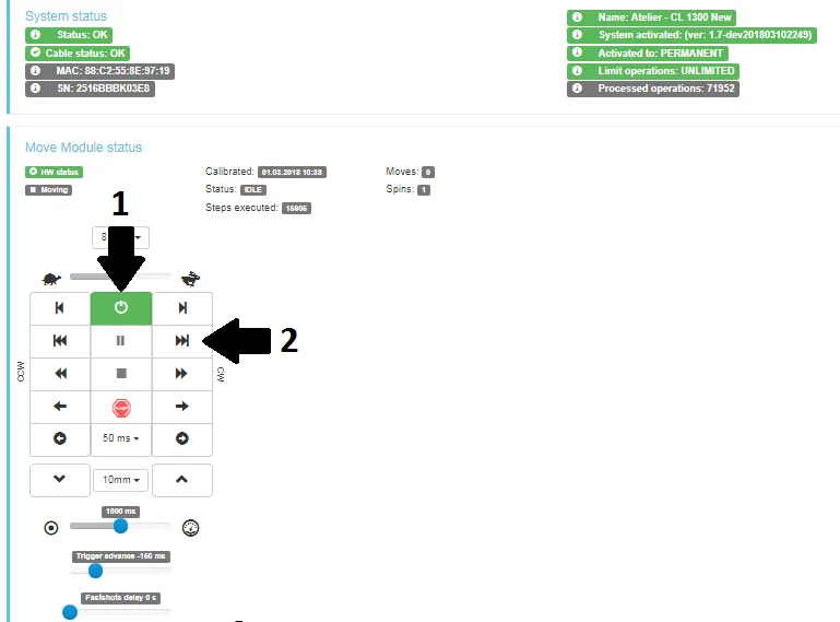
- Įjunkite variklius (rodyklė 1) ir pabandykite valdyti bet kurią judančią roboto dalį (rodyklė 2).
- Jei robotas juda pagal jūsų instrukcijas, jūsų "PhotoRobot" įrenginys yra paruoštas įprastam naudojimui.
4. PhotoRobot _Controls programos programinė įranga
"Frame" robotinė darbo vieta valdoma naudojant "PhotoRobot _Controls App" programinę įrangą. "_Controls App" programinę įrangą galite atsisiųsti iš savo PhotoRobot paskyros. Tai nėra mašinos pristatymo dalis; Jis perkamas atskirai nuo mašinos.
Nata: "PhotoRobot Controls" programos diegimo ir naudojimo instrukcijas rasite "PhotoRobot Getting Started" vartotojo vadove.
5. Informacinės etiketės
5.1. Simbolių apžvalga
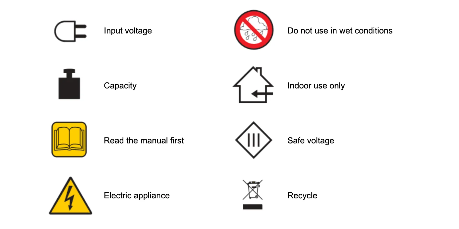
5.2. Mašinų ir komponentų etiketės
Konkrečių mašinų ir komponentų etiketes rasite dokumente "PhotoRobot saugos informacija ir instrukcijos" skyriuje "Informacinės etiketės" (3.1.).


EOS sukilėlių serija


EOS DSLR serija


EOS M serija be veidrodžių


"PowerShot" serija


Iš arti / delninis

"Canon EOS Rebel" serija siūlo pradedantiesiems pritaikytus DSLR fotoaparatus su tvirta vaizdo kokybe, intuityviu valdymu ir universaliomis funkcijomis. Šie fotoaparatai, idealiai tinkantys fotografijos entuziastams, užtikrina patikimą automatinį fokusavimą, įvairaus kampo jutiklinius ekranus ir "Full HD" arba 4K vaizdo įrašymą.
Ryšys
Skiriamoji geba (MP)
Rezoliucija
"Canon EOS DSLR" serija užtikrina aukštos kokybės vaizdus, greitą automatinį fokusavimą ir universalumą, todėl idealiai tinka tiek fotografijai, tiek vaizdo įrašų gamybai.
Ryšys
Skiriamoji geba (MP)
Rezoliucija
"Canon EOS M Mirrorless" serija sujungia kompaktišką dizainą su DSLR panašiu našumu. Šios kameros su keičiamais objektyvais, greitu automatiniu fokusavimu ir aukštos kokybės vaizdo jutikliais puikiai tinka keliautojams ir turinio kūrėjams, ieškantiems perkeliamumo neprarandant vaizdo kokybės.
Ryšys
Skiriamoji geba (MP)
Rezoliucija
"Canon PowerShot" serija siūlo kompaktiškas, patogias kameras atsitiktiniams šauliams ir entuziastams. Su modeliais nuo paprastų taškų ir fotografavimo iki pažangių priartinimo kamerų, jie užtikrina patogumą, tvirtą vaizdo kokybę ir tokias funkcijas kaip vaizdo stabilizavimas ir 4K vaizdo įrašas.
Ryšys
Skiriamoji geba (MP)
Rezoliucija
"Canon" stambiu planu ir rankiniai fotoaparatai yra skirti detaliam, artimam fotografavimui ir vaizdo įrašams. Kompaktiški ir paprasti naudoti, jie siūlo tikslų fokusavimą, didelės skiriamosios gebos vaizdą ir universalias makrokomandų galimybes – puikiai tinka vaizdams rašyti tinklaraščius, fotografuoti produktus ir kurti stambiu planu.


